Philco 48-461 radio restoration

 Philco 48-461 radio restoration
I am currently restoring an antique radio (Philco 48-461). Both the electronics and the cabinetry; gotta love the era of wooden radios. Sherman got me interested in it. Of course I used to work for Rockwell, Siemens, and STmicroelectronics so electronics is somewhat in my wheelhouse, or should we say my bailiwick. My dad was an engineer with a basement radio lab in the 50's when I was growing up. Oh, the memories being retriggered, not least of which is the great fragrance of slowly melting paper-wax capacitors, and cooking tube dust. But don't worry, I'll try to split time between this and the multimedia coding, etc. Software is so sterile.
Philco 48-461 radio restoration
Happy to oblige, big t.
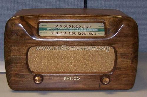
Here is a sample of the 48-461 from the radio museum. Sort of a futuristic look for 1948, deviating from the traditional cabinet styles, such as cathedral and tombstone. Wow factor for the neighbors. The light color finish is unusual and most had a dark brown lacquer finish. Mine was the dark brown but had terrible flaws in the finish which meant it had to be stripped and refinished. I also had to repair the cabinet as it had several open joints. There were clamp marks from a random idiot trying to fix it (badly). I was able to steam those out and now the cabinet looks great pending finishing (see below). Ouch, that tuning dial is a bit crooked, I could do way better.
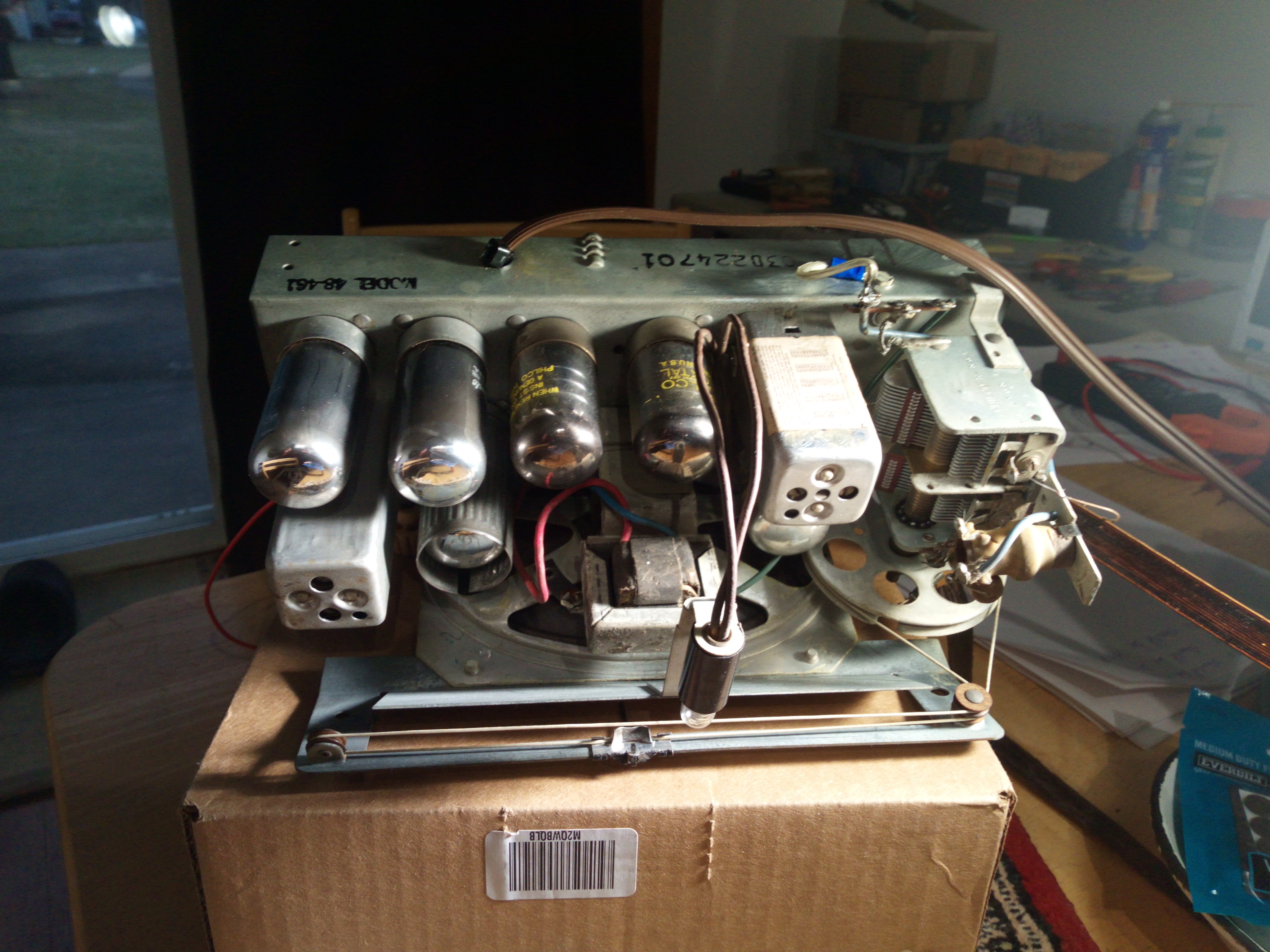
Here is the tube side of my unit. I've replaced the line cord, which was dangerously degraded.
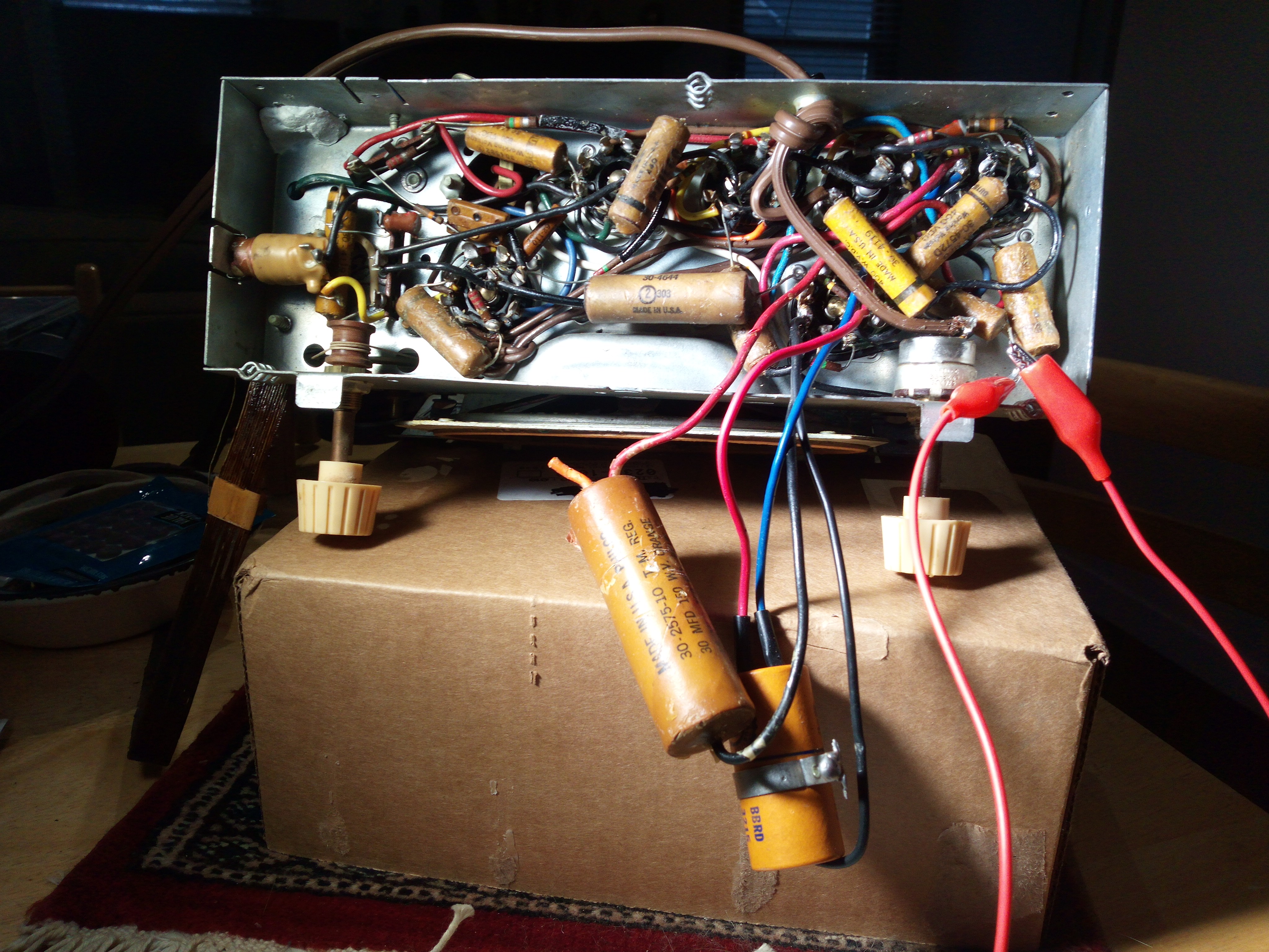
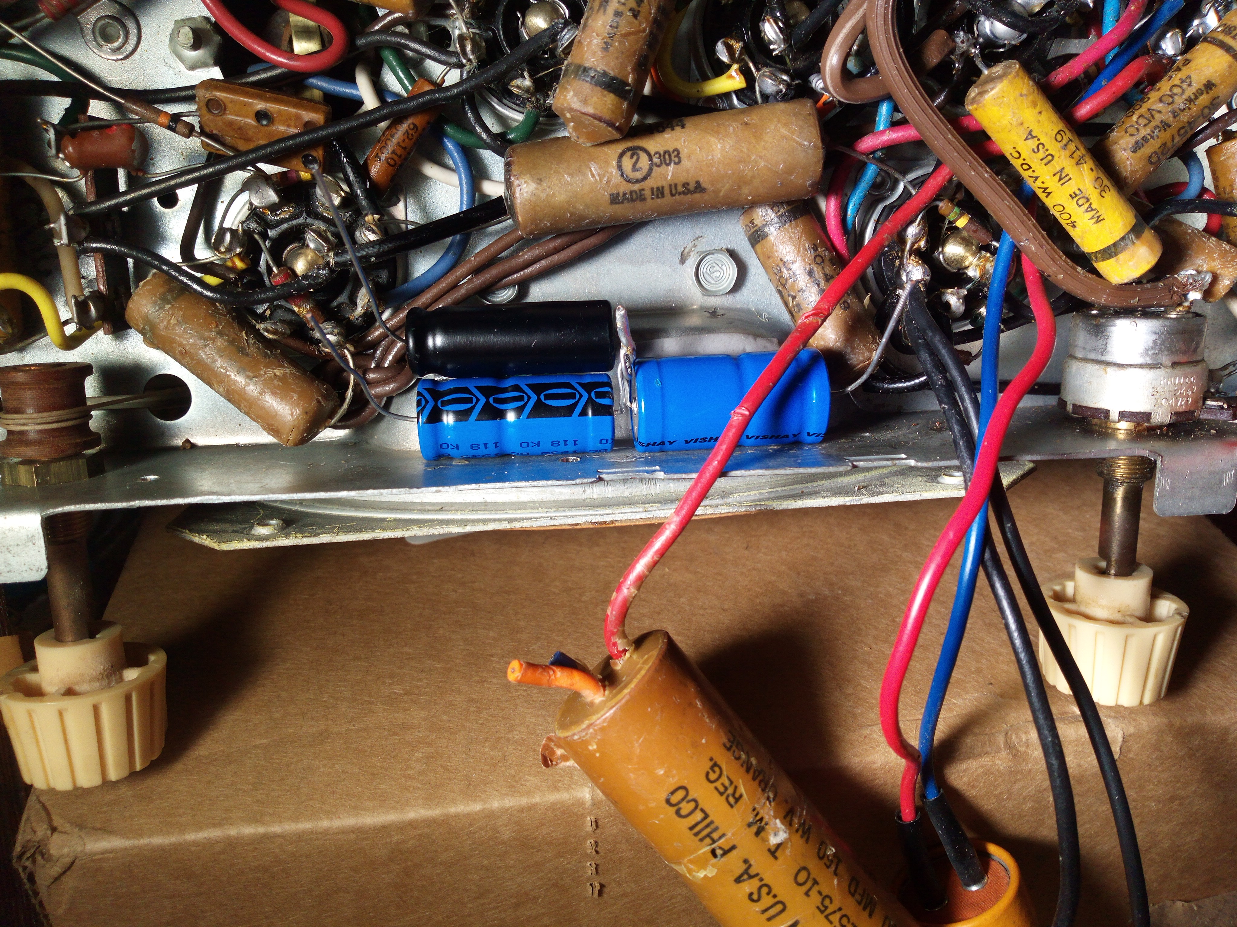
And here is the bottom. You can see the dangling electrolytic caps that will be replaced today. Also, you can see lots of paper-wax capacitors that need to be replaced.
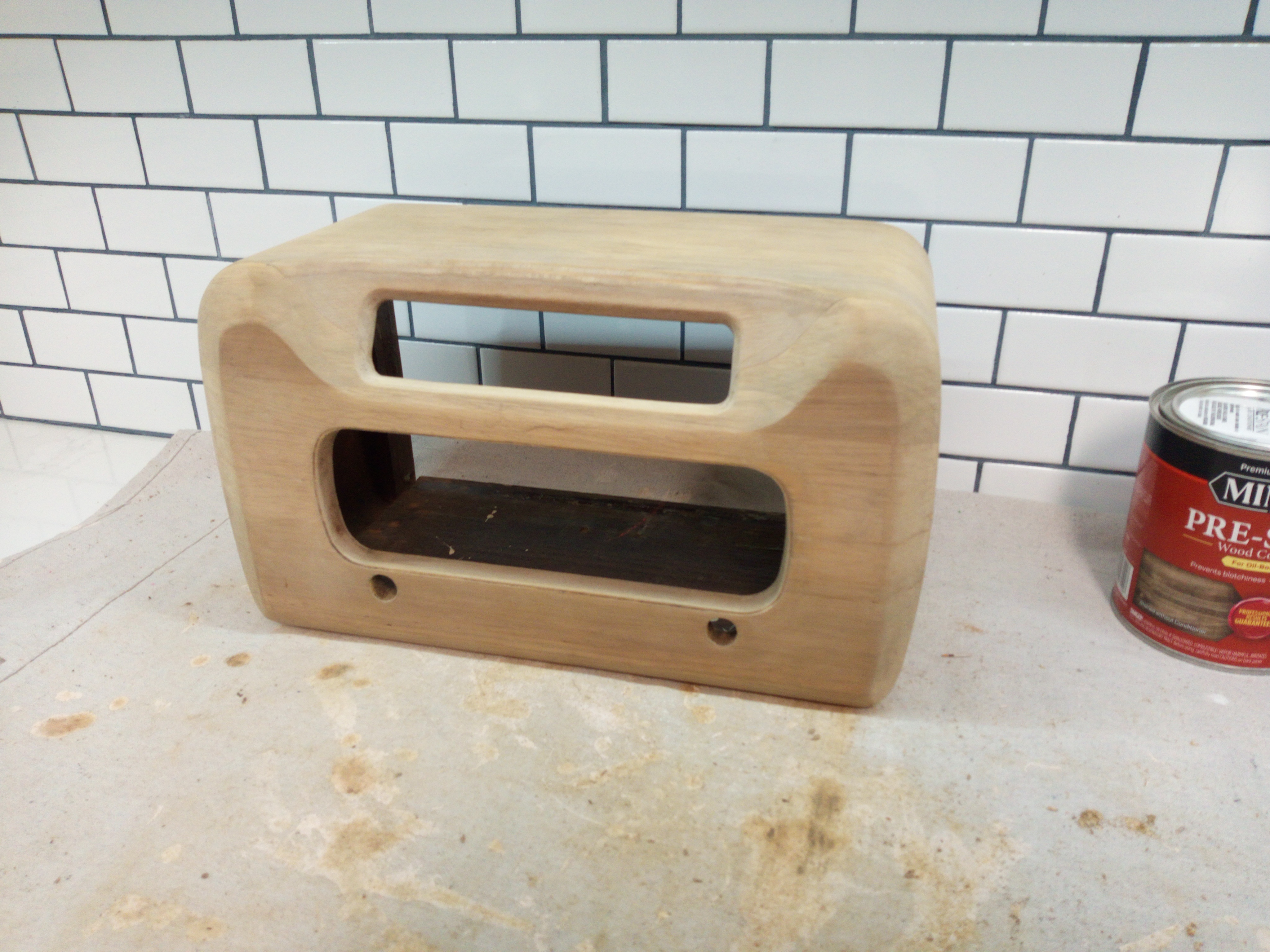
Here is my unit's cabinet stripped and ready for finishing. I'm going to go with a mahogany stain.
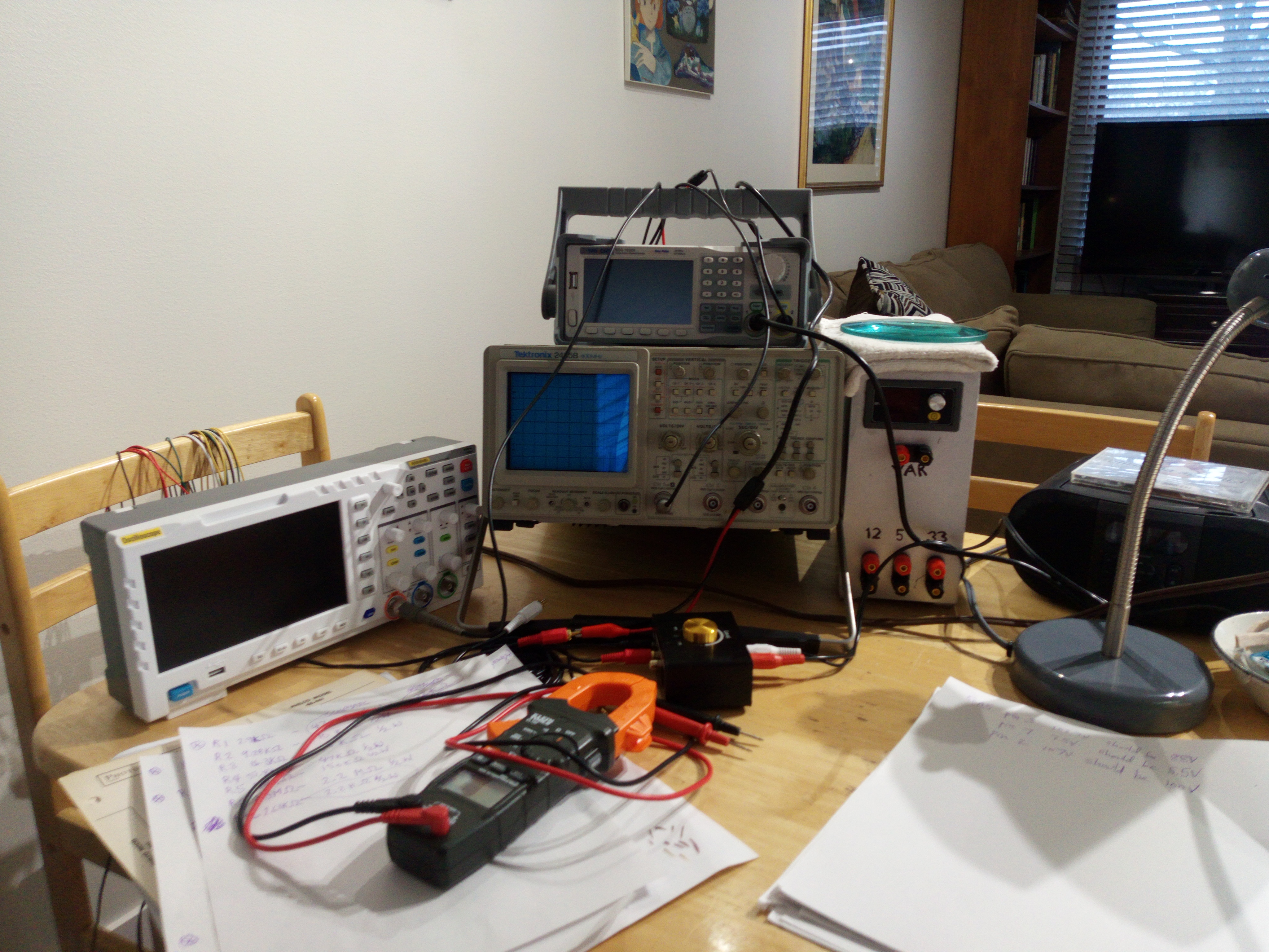
And finally, my little lab area on the dining room table.
The current issues are not too bad. Other than these two the radio works fine.
1. Even on lowest volume the sound is too loud. The B+ voltage is too high, overdriving the audio output. My FLIR camera confirms the audio output tube is overdriven. The set was originally run at 105Vac in 1948 while my current mains supply is 124Vdc. So that alone can account for it. I have a variac on order to test that theory. However, the resistors in that stage have drifted so I will assess things after replacing those and the paper-wax caps. I may need to drop the line voltage through a resistor. The potentiometer itself has significantly lower resistance than it should; that could also be the cause. Will assess after the components are replaced.
2. The dial lamp is too dim and needs replacing.
Here is a sample of the 48-461 from the radio museum. Sort of a futuristic look for 1948, deviating from the traditional cabinet styles, such as cathedral and tombstone. Wow factor for the neighbors. The light color finish is unusual and most had a dark brown lacquer finish. Mine was the dark brown but had terrible flaws in the finish which meant it had to be stripped and refinished. I also had to repair the cabinet as it had several open joints. There were clamp marks from a random idiot trying to fix it (badly). I was able to steam those out and now the cabinet looks great pending finishing (see below). Ouch, that tuning dial is a bit crooked, I could do way better.
Here is the tube side of my unit. I've replaced the line cord, which was dangerously degraded.
And here is the bottom. You can see the dangling electrolytic caps that will be replaced today. Also, you can see lots of paper-wax capacitors that need to be replaced.
Here is my unit's cabinet stripped and ready for finishing. I'm going to go with a mahogany stain.
And finally, my little lab area on the dining room table.
The current issues are not too bad. Other than these two the radio works fine.
1. Even on lowest volume the sound is too loud. The B+ voltage is too high, overdriving the audio output. My FLIR camera confirms the audio output tube is overdriven. The set was originally run at 105Vac in 1948 while my current mains supply is 124Vdc. So that alone can account for it. I have a variac on order to test that theory. However, the resistors in that stage have drifted so I will assess things after replacing those and the paper-wax caps. I may need to drop the line voltage through a resistor. The potentiometer itself has significantly lower resistance than it should; that could also be the cause. Will assess after the components are replaced.
2. The dial lamp is too dim and needs replacing.
-
Guest

Philco 48-461 radio restoration
Would you consider a red oak stain?
Is that a greenlee meter you are using?
Is that a greenlee meter you are using?
Philco 48-461 radio restoration
Want to get close to the original color so red oak is out. My interior scheme is all cherry, mahogany, and gunstock oak, so red oak would be a sore thumb.
In the photo there is a cheapo Klein clamp-on meter, a cheapo plastic scope, a great Tektronix 2465B scope, and a Siglent signal generator on top of the 2465B.
To the right of the 2465B is a bench power supply I made myself from an old PC power supply and a buck-boost controller to supply the VARiable output. Don't you love the lettering (Bullwinkle did that).
For fun, I cooked up an AM transmitter using the Siglent and a small audio pre-amp (small black box with the gold knob on top):
CD player -> audio pre-amp -> external modulation input of Siglent
Siglent main output set to 1500 KHz with external modulation and connected to antenna.
It is easily received everywhere in my house and about halfway down the driveway. I'm going to build a smaller
self-contained transmitter and send old-time radio streams to the antique radios.
Philco 48-461 radio restoration
Here are the replacement electrolytic capacitors mounted and prepped for wiring. Mounted using modern miracle adhesives.
And here are the lytics all wired and happy. Radio still works so that's good. Oops, didn't have any blue wire on hand. Not the greatest work ever done by man, woman, or squirrel, but it's out of sight, out of mind, ya know.
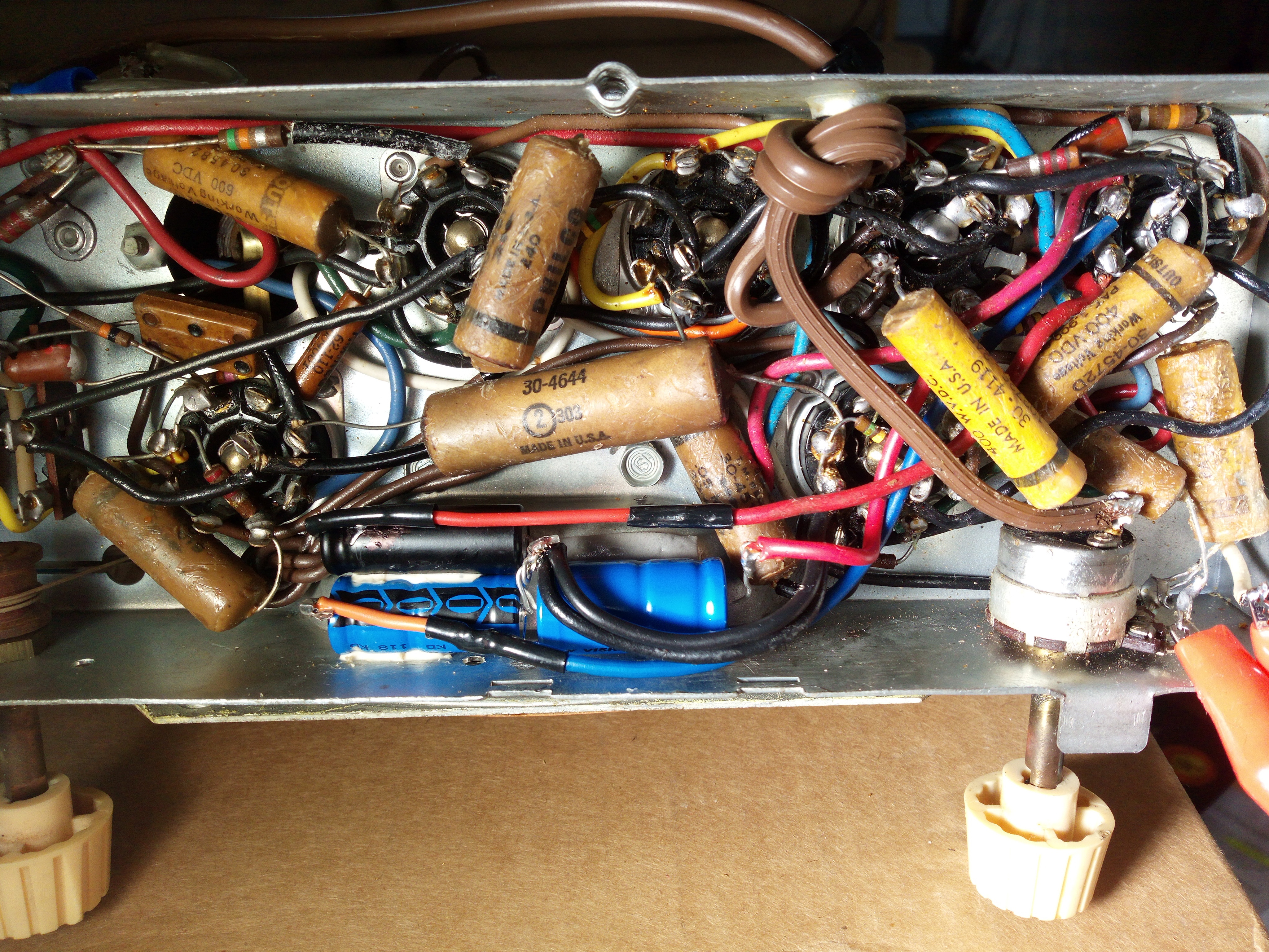
Now let's recap and replace out-of-tolerance resistors in the audio output stage.
And here are the lytics all wired and happy. Radio still works so that's good. Oops, didn't have any blue wire on hand. Not the greatest work ever done by man, woman, or squirrel, but it's out of sight, out of mind, ya know.
Now let's recap and replace out-of-tolerance resistors in the audio output stage.


Philco 48-461 radio restoration
Your evil plans will not succeed!
Great job, Rocky. Do you want me to look into the hot audio?
Great job, Rocky. Do you want me to look into the hot audio?
Philco 48-461 radio restoration
Don't you have some wall warts to kill, Shermie? Leave this to the grown-ups.
Philco 48-461 radio restoration
Good progress! The variac came in today so I set it for 110Vac, which was sort of a standard in the 1930/40s. The service manual shows the acceptable input range as 105v-120v. My house has 127Vac. This reduction in line voltage greatly reduced the audio volume as desired but not enough. It did greatly reduce the tube temperatures helping with lifetimes. I wanted the audio almost inaudible at the lowest volume setting. I had previously noted that the volume pot was way down in resistance, so I decided to patch in a resistor at the top of the pot to bring its total resistance back nearer to original. Getting a replacement pot is difficult while rebuilding it is still an option. Anyway, the top half of the pot was not used. The result with the resistor and cleaning the pot with contact cleaner was satisfactory. The volume is very low at the lowest setting and comes up nicely as the control is increased. Philco experts say that it was designed not to go to zero volume so you always knew it was on. Still, this works only at a 110Vac line voltage so we need a solution to that short of strapping the variac to the side of the cabinet. The solution is either a buck transformer or a power series resistor on the line input. I'm researching the choice on that now. Then I am thinking of replacing the bulb with an led. Out of sight, out of mind?

-
Guest
Philco 48-461 radio restoration
I would say power series resistor
Buck transformer will fluctuate with input V
Resistor might be more linear (?) in attenuating the voltage
Buck transformer will fluctuate with input V
Resistor might be more linear (?) in attenuating the voltage

Philco 48-461 radio restoration
Yeah, that's the stuff we need to look at. Did you notice one wax-paper cap got replaced? Just like spot the differences. Nyuk.
Sherm told me you could also use a capacitor or diode solution but that's woo-woo for me. We should ask Wonder Woman. Nyuk. Nyuk.
Oh and shut up about the vintage multimeter. A family hairloom for the harem. OK?
Sherm told me you could also use a capacitor or diode solution but that's woo-woo for me. We should ask Wonder Woman. Nyuk. Nyuk.
Oh and shut up about the vintage multimeter. A family hairloom for the harem. OK?
Philco 48-461 radio restoration
Pimp it out hidden inside the chassis. Like, add some anti-hiss (the old "shhhh" problem) and bass enhancement circuitry. Gotta think outside the box. That's what Balti told me. So here goes. We add a small fan to the radio just like a PC enclosure. It can be under the chassis opening to the bottom like a PC power supply. External restoration internal pimping.
-
Bullwinkle

- Posts: 344
- Joined: Thu Sep 05, 2019 6:37 pm
Philco 48-461 radio restoration
All options are on the table. You can tell them I told you.

Philco 48-461 radio restoration
DG wants a dropping resistor. There just is no good place for a bucking transformer. So I ordered two chassis-mount power wire-wound resistors: a 12 ohm 30 watt and a 22 ohm 30 watt. Measured current on the line input and then back of the envelope calculation says 10 ohms so let's see. If it gets too hot we can revisit things, or put in a fan. 
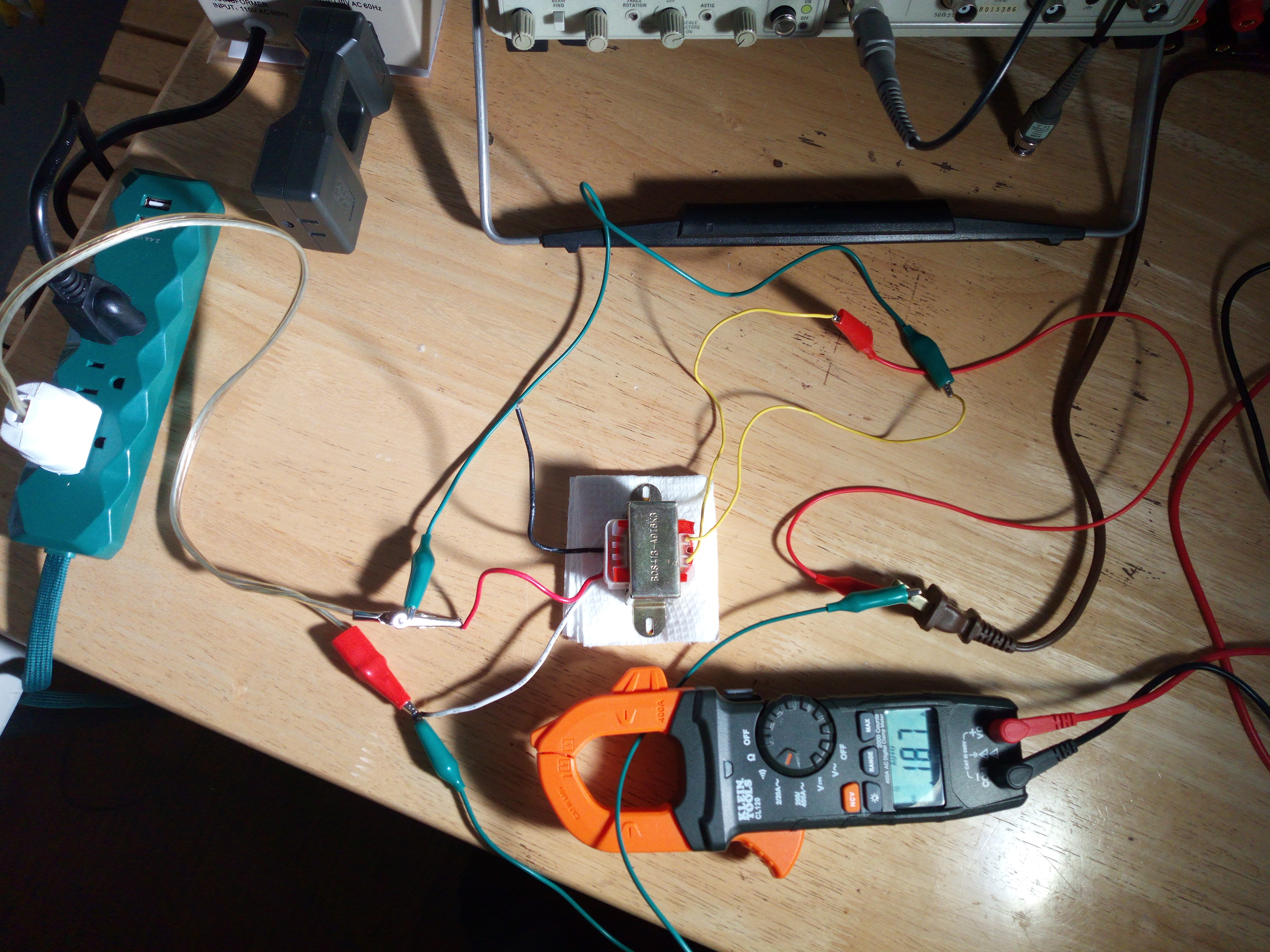
I'm a little concerned at the line current of 1.8A. Would like it less than an amp. Gonna look into that. That's why I got the 22 ohm resistor too. If I reduce the current draw a bigger resistor is required.
Also I put a cap and pot in series across the plate of the audio output tube to B-, giving us a primitive tone control. It is quite effective in getting rid of the tinny shhhshy sound and lending a bit more solidity to the sound. I never agreed with trying to use strong highs to pretend to overcome the limited AM channel bandwidth. One option is to mount the tone control on the back of the chassis with access from the existing cutout on the back. It's in the back...out of sight out of mind. Or maybe better just choose a good fix value and ditch the pot. That's more authentic and less damaging to the original.
Now researching the dial lamp issue. Of course it is even dimmer with the line voltage reduction.
Was thinking about gaps correction for TrueHD with AC3 core. I know what to do and it shouldn't be too bad.
Philco 48-461 radio restoration
Thanks for your photos and work in progress.
I think I still have 3 or 4 of that old radios in my grandma's home, some still prefectly working.
Some have a graphite resistor, glowing red hot when turning on. Fascinating.
I think I still have 3 or 4 of that old radios in my grandma's home, some still prefectly working.
Some have a graphite resistor, glowing red hot when turning on. Fascinating.
Philco 48-461 radio restoration
Ordered a small bucking transformer that can fit in there. So we can test both solutions. Tried to find a resistive line cord but they stopped making them in the 50s. They were called curtain burners so they must have been phased out for safety reasons. Ya think?
Did some tests and this radio works best at 100Vac. The filament voltages are all rather low (which is good) and the receiver sensitivity and audio still sound just fine. So I'm going to try bucking off 24Vac.
Still trying to figure out the current draw situation. The specs say 26 watts for this radio which should be well less than 1/2 A, but my clamp-on meter says 1.8 A (~180 watts!). I think something must be wrong there so I ordered a kill-a-watt to test the power directly. I disconnected B+ and the draw diminished to 1.4 A which is absurd for just the tube filament string. Tubes are not that hot so I can't believe they are drawing 1.4 A. Already checked relevant caps with no issues. Hmmm.
Philco 48-461 radio restoration
Got some exciting results. Found a transformer in my junk box from an old cheapo boom box. I was able to buck 14Vac from the line. Main thing is the clamp-on meter shows 0.19 A, which means low 20's wattage. Not sure what was going on with the clamp-on on the variac output. So, it's cool? Not so fast. That transformer is very toasty. Can't hold a finger to it. How would that compare to a series resistance? We shall see. Maybe a fan is not so outrageous an idea. I'm thinking now the method doesn't matter, we just have to burn off the extra power.
Philco 48-461 radio restoration
There you go big t, always trying to complicate things.
Silly me. The Klein clamp-on adapter thingie is x10, so we had 0.18 amps all along. Now we'll probably need more resistance for our dropping resistor.
Meanwhile I had an idea about light dimmers. Worth a try, or will it be noise city?
Silly me. The Klein clamp-on adapter thingie is x10, so we had 0.18 amps all along. Now we'll probably need more resistance for our dropping resistor.
Meanwhile I had an idea about light dimmers. Worth a try, or will it be noise city?
Philco 48-461 radio restoration
Honestly, connected directly in the line I don't think any shielding is going to help. I just tried a standard one and noise city is a gross understatement. Gotta be an analog solution IMSO (in my squirrel opinion).